
Bitaxe hardware faults: what Power Fault, the self-test and chip count 0 really mean
6 November 2026 · 27 min read

A Bitaxe reports hardware problems in three places: on its small display, as a red line in the AxeOS dashboard and in the log. The messages are short and sometimes misleading. “Power Fault Detected. Check your Power Supply.”, for example, also appears when the power supply is perfectly fine. This article explains every hardware message in AxeOS: what it means technically, which part it comes from and what to check before you assume a defect. It is based on the source code of AxeOS 2.15.4, the current release from 21 October 2026 (this part is identical in 2.15.3), the datasheet of the Texas Instruments TPS546D24A voltage regulator and the open hardware files of the Bitaxe Gamma. It contains no measurement series of our own. Where we draw conclusions from the code that nobody has measured, we say so.
- Which message means what?
- Five steps to the cause
- Where faults come from: the power path in the Gamma
- “Power Fault Detected”: what the voltage regulator reports
- Checking the voltage under load: the pause test
- The self-test: what it checks and how to start it
- “ASIC 0 not found” and chip count 0
- Overheating: chip, regulator and the AxeOS protection
- Fan: “Fan Control Failed” and FAN:WARN
- Restarts: what Reset Reason tells you
- When it is a case for support
- Frequently asked questions
Which message means what?
The table lists the hardware messages AxeOS 2.15.4 can show on the Gamma, GT, Supra Hex and Gamma Hex, and where you see them. The texts appear exactly like this in the source code; only numbers and chip indices change from device to device. Messages about pools and Wi-Fi such as “Using fallback pool” are not included here; those are covered in Bitaxe on Wi-Fi but not mining. Where each card and page sits in AxeOS is shown in AxeOS explained. Nerdaxe, NerdQaxe and NerdOctaxe run NerdOS and use their own texts; the basics of the power path apply to them, the individual messages do not.
| Message | Where | What it means | First step |
|---|---|---|---|
Power Fault Detected. Check your Power Supply. | Dashboard | The voltage regulator reported a fault or delivers no core voltage. The cards then show Not available - Power fault. | Read the TPS546 lines in the log, Power Fault |
Danger: Low Voltage | Dashboard, Power card | Input voltage below 94.9 % of nominal: below 4.75 V on the Gamma, below 11.39 V on 12 V devices. | Check power supply, cable and plug, pause test |
ASIC STATUS: ASIC 0 not found | Display | The hashing chip did not answer at boot, mining does not start. | ASIC not found |
0 chip(s) detected on the chain, expected 1 | Log | The same as a log line. This is where the search term “chip count 0” comes from. | as above |
CHIP_ID response mismatch: expected 0x1368, got 0x1370 | Log | A chip answers, but a different type than expected. Firmware and board do not match. | Check Board Version on the System page |
Unexpected ASIC 1 detected | Display | More chips than the firmware expects, another sign of the wrong board version. | as above |
DEVICE OVERHEAT! and Device has overheated - See settings | Display, dashboard | The overheat protection tripped: chip above 75 °C or regulator above 105 °C. Frequency and voltage have been lowered. | Overheating |
Danger: High Temperature | Dashboard | Chip at 70 °C or more, or regulator at 105 °C or more, not yet shut down. | Check cooling and frequency |
Fan Control Failed (Auto) | Dashboard | The firmware could not set the fan speed and stops mining. | Fan |
BITAXE SELF-TEST | Display | The self-test is running, started with the BOOT button or after a factory reset. | wait, self-test |
SELF-TEST FAIL! with a code such as VCORE:PWR FAULT | Display | A check failed; the code names it. | Self-test checks |
Brownout reset (software or hardware) | System page, Reset Reason | The ESP32’s supply dipped briefly and it restarted. | Restarts |
Device frequency is set low - See settings | Dashboard | Frequency below the lowest preset, below 400 MHz on the Gamma, usually after several overheat events. | Set Frequency back to “(Default)” |
Five steps to the cause
With hardware messages, a fixed order pays off. Each step rules out or confirms a whole group of causes, and the first four only need a browser on the same network as the miner.
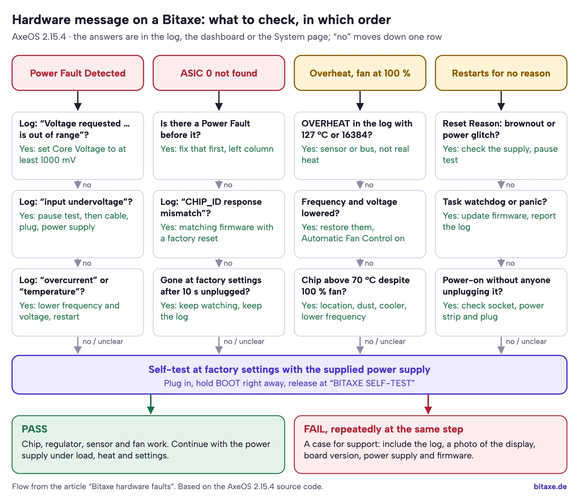
- Write the message down. Take a photo of the display and the dashboard before you restart. A Power Fault disappears with the restart even if its cause remains.
- Save and read the log. On the Logs page, “Download Logs” saves the log. It lives in the ESP32’s external RAM (PSRAM) and, according to the code, survives a software restart, including a crash; once you unplug the power supply it is empty. Search for “TPS546” for the voltage regulator, “OVERHEAT” for the heat protection, “chip(s) detected” for chip detection and “Fan Control” for the fan.
- Look at Reset Reason. The System page shows why the miner last restarted. A brownout points to the power supply, a watchdog or crash to the firmware.
- Check the voltage under load. With the pause test you see within two minutes how much voltage the power supply, cable and plug lose under load.
- Run the self-test. It checks at factory settings, without a pool and without Wi-Fi, whether chip, regulator, sensor and fan work.
Only if the self-test fails at factory settings with the supplied power supply does a board defect become likely. What to send to support is described at the end. If you prefer to be guided step by step, use the miner troubleshooter; it also covers Wi-Fi and pool problems.
Where faults come from: the power path in the Gamma
For troubleshooting, a rough picture of the board is enough. We use the Bitaxe Gamma as the example because its schematics are open on GitHub and it is the entry model of the family.
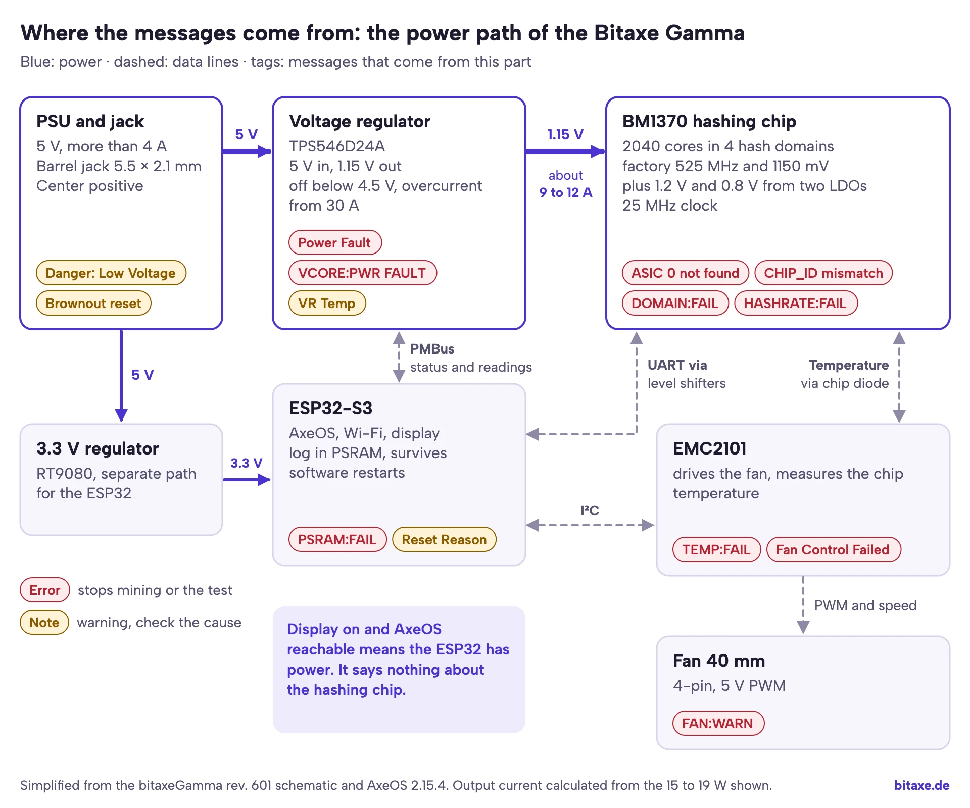
Power comes in through a round 5.5 × 2.1 mm barrel jack at 5 V, center positive. The project’s hardware documentation is blunt about it: “5V DC Only! Anything else will damage the Bitaxe.” The power supply should deliver more than 4 A (20 W) without dropping below 5 V; 25 to 30 W is recommended.
From the jack, two separate paths branch off. The first leads to the TPS546D24A voltage regulator. It turns 5 V into the core voltage of the hashing chip, 1.15 V at factory settings. According to its datasheet it accepts 2.95 to 16 V at the input and up to 40 A at the output, and several can be stacked up to 160 A. Over a two-wire bus, PMBus, it reports input voltage, output voltage, current, its own temperature and every fault to the ESP32. Almost all power-related messages in AxeOS come from it.
The BM1370 hashing chip has 2040 small cores in four hash domains, which AxeOS shows individually in the “Hashrate Registers” card; how to read them is explained in Bitaxe hashrate error. Two small linear regulators additionally supply 1.2 V and 0.8 V to it. It talks to the ESP32 over a serial line (UART), with level shifters in between because both sides work at different voltages. A 25 MHz oscillator provides the clock.
The second path runs through a separate 3.3 V regulator to the ESP32-S3. It runs AxeOS, keeps the Wi-Fi connection, drives the display and reads the sensors. This leads to an important rule for diagnosis: if the display is on and AxeOS responds, the ESP32 has power. That says nothing about the hashing chip. During a Power Fault the ESP32 keeps running and can report the fault. If the input voltage drops so far that the ESP32 loses power too, it restarts and reports a brownout.
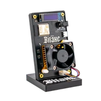
The EMC2101 controls the fan and measures the chip temperature through a diode inside the BM1370. If it does not respond, AxeOS reports invalid temperatures or “Fan Control Failed”. The fan is a 40 mm model with four pins and 5 V PWM.
The other models follow the same principle with 12 V at the input. The Bitaxe GT has two chips and a two-phase regulator, the Gamma Hex 1300 six chips and a four-phase one. On the Supra Hex 702, three voltage domains sit in series, so its regulator outputs roughly three times the chip voltage. The messages are the same; only the limits differ.
“Power Fault Detected”: what the voltage regulator reports
Behind the message is a single query. AxeOS keeps reading the TPS546’s status word, a 16-bit register defined by the PMBus standard. If one of five bits is set, it counts as a Power Fault: regulator off (OFF), output overvoltage (VOUT_OV), output overcurrent (IOUT_OC), input undervoltage (VIN_UV) or a temperature problem (TEMP). The dashboard shows the same sentence in all five cases because the text is hard-coded in the firmware. Which case you have only shows in the log: on the first occurrence, AxeOS writes a snapshot of all status registers once, plus one plain-text line per set bit.
A sixth bit for communication, memory and logic faults (CML) does show up in the log as “A communication, memory, logic fault has occurred”, but it does not trigger a Power Fault.
The five shutdown reasons in the log
Filter the Logs page for “TPS546”. The first line reads “Status: 0x…”, followed by the explanations:
| Log line | What the regulator reports | Typical cause | What helps |
|---|---|---|---|
An input undervoltage fault has occurred, often with VIN Low Voltage or VIN Undervoltage Warning | The input voltage fell below the shutdown threshold, 4.5 V on the Gamma. | Power supply too weak, thin or long cable, barrel plug with contact resistance, power strip | Pause test, then replace cable, plug or power supply |
An output overcurrent fault has occurred, with IOUT Overcurrent Fault | More current flowed at the output than allowed, 30 A on the Gamma. | Frequency and voltage far above factory settings, rarely a short | Lower the settings, then restart; the regulator does not come back on its own |
An output overvoltage fault has occurred, with VOUT Overvoltage Fault | The core voltage was more than 25 % above the setpoint. | rare, a control problem or a defect | Restart; if it returns at factory settings, contact support |
A temperature fault/warning has occurred, with Overtemperature warning or Overtemperature fault | The regulator itself is too hot: warning from 105 °C, shutdown from 145 °C. | High load, warm room, little airflow across the board | Lower frequency and voltage, improve cooling |
only The voltage regulator is turned off | The regulator is not converting, without any of the four faults. | usually a core voltage outside the allowed range; then the line before it reads Voltage requested (0.980000 V) is out of range | Core Voltage to at least 1000 mV, see below |
With undervoltage, overcurrent and overvoltage, “The voltage regulator is turned off” usually appears as well, because the regulator shuts down in those cases. What matters is the line next to it.
Regulator limits by model
AxeOS writes the thresholds into the regulator at boot. This is how they are set in firmware 2.15.4:
| Device | Regulator starts at | shuts down below | Input overvoltage from | Overcurrent warning / shutdown | Allowed output voltage |
|---|---|---|---|---|---|
| Gamma 601 to 603, Gamma Copper Pro | 4.8 V | 4.5 V | 6.5 V | 25 A / 30 A | 1.0 to 2.0 V |
| GT 801 | 11.0 V | 10.5 V | 14.8 V | 50 A / 55 A | 1.0 to 3.0 V |
| Supra Hex 702 | 11.5 V | 11.0 V | 14.8 V | 25 A / 30 A | 2.5 to 4.5 V (three domains in series) |
| Gamma Hex 1300 | 11.0 V | 10.5 V | 14.0 V | 150 A / 160 A | 2.0 to 3.0 V (two domains in series) |
The temperature limits are the same for all: warning from 105 °C, shutdown from 145 °C. The input overvoltage limit is a protection threshold, not a permission. A 12 V power supply never belongs on a Gamma, even if the plug fits. Which power supply goes with which model, and why the Gaia and the Gamma share the same plug at different voltages, is covered in Power supply for Bitaxe.
The overcurrent value looks high because it applies to the output side: at 1.15 V, a multiple of the power supply current flows there. An example with the Gamma’s factory settings: AxeOS shows 15 to 19 W. That includes a flat 5 W for the rest of the board (more on that in the next section), so 10 to 14 W reach the chip. Divided by 1.15 V, that is roughly 9 to 12 A. Up to the shutdown at 30 A there is more than twice that headroom. Anyone who gets there has raised frequency and voltage far above the factory settings.
Why the message stays until you restart
The TPS546’s fault bits are latched. According to the datasheet they stay set until the CLEAR_FAULTS command clears them; if the cause is still present, the regulator sets them again immediately. AxeOS sends this command only at boot: it switches the regulator off, clears the faults and switches it back on with the configured voltage. As a result:
- A Power Fault only disappears with a restart, even if the cause is long gone, such as a briefly loose plug.
- If it comes back right after the restart, the cause is permanent: an invalid core voltage, a power supply that collapses at startup, or a defective regulator.
- If it only comes back after minutes under load, that points to undervoltage under load or heat.
- After an overcurrent fault the regulator stays off. AxeOS configures it to shut down without restarting in that case. With overtemperature, on the other hand, it waits until it has cooled down and restarts on its own.
The trap below 1000 mV
One cause of a Power Fault has nothing to do with the power supply and is easy to fix yourself. The Gamma’s regulator only accepts core voltages from 1.0 to 2.0 V. If AxeOS requests less, the log shows “Voltage requested (0.980000 V) is out of range”, the regulator stays off and the dashboard reports “Check your Power Supply”. Because the chip cannot answer without core voltage, the display additionally shows “ASIC 0 not found” after the next boot; that follows from the startup order in the code.
A Gamma ends up there in two ways: someone sets less than 1000 mV while undervolting, or the overheat protection subtracts a flat 100 mV from a value that was already low. Up to and including AxeOS 2.15.4, any value below 1100 mV becomes one below 1000 mV after an overheat event, and because AxeOS saves the lowered value, the fault persists across every restart. The fix has been in the development branch since September 2026 (pull request 1790), but not yet in a release. The remedy: under Settings, set Core Voltage to at least 1000 mV, then Save and Restart.
Checking the voltage under load: the pause test
Whether power supply, cable and plug have enough headroom, AxeOS shows you itself if you compare two values: the input voltage without load and with load. The regulator measures it at its input, that is after the power supply, cable and jack. The difference is the voltage lost along exactly that path.
- In the dashboard, read the Input Voltage in the Power card while the miner is hashing. Wait a few minutes after boot.
- Pause mining with the “Pause Mining” icon at the top right. AxeOS switches off the core voltage, so the chip draws no more current. Read the Input Voltage again after a few seconds.
- Resume mining with “Resume Mining” and note both values. In the chart you can also show the “Voltage” curve and follow it over hours.
If the value does not change during the pause, measure the power supply’s voltage without load with a multimeter at the barrel plug, center positive, outer sleeve negative. That replaces the value from step 2.
Worked example: how much headroom does the supply path have?
An example with assumed values, not a measurement: paused 5.15 V, hashing 4.90 V, power according to AxeOS 17 W.
| Quantity | Calculation | Result |
|---|---|---|
| Voltage loss under load | 5.15 V − 4.90 V | 0.25 V |
| Current from the power supply, estimated | 17 W ÷ 4.90 V | about 3.5 A |
| Resistance of power supply, cable and plugs combined | 0.25 V ÷ 3.5 A | about 0.07 Ω, i.e. 70 milliohms |
| Margin to the “Danger: Low Voltage” warning | 4.90 V − 4.75 V, divided by 0.07 Ω | 0.15 V, about 2 A more current |
| Margin to the regulator shutdown | 4.90 V − 4.50 V, divided by 0.07 Ω | 0.40 V, about 5.5 A more current |
AxeOS does not show the current from the power supply directly. On the Gamma, “Current” in the Power card is the current at the regulator output, that is on the chip side, and “Power” is its output power plus a flat 5 W for the rest of the board. Both are defined like this in the source code. Estimating via power divided by voltage is therefore rough, but good enough for an estimate.
The model is simplified as well: it treats the power supply and cable like a fixed resistance. Real power supplies regulate, and very short dips do not show up in the display. A useful yardstick is the requirement from the hardware documentation: not below 5 V under load. The example with 4.90 V narrowly misses it. In that case, a short, heavy cable and a firmly seated plug help first, then a stronger power supply. How cable length and cross-section determine the loss, and what applies to several miners on one power supply, is calculated in Power supply for Bitaxe.
The self-test: what it checks and how to start it
The self-test is the best tool to separate hardware from settings. It runs independently of your settings at the chip’s factory values, needs neither Wi-Fi nor a pool because it generates its own work, and checks chip, regulator, temperature sensor and fan one after another. On the Gamma the chip runs at 525 MHz and 1150 mV during the test, even if you normally overclock.
Starting the self-test
There are two ways. Automatically after a factory reset: If you install the firmware with flasher.bitaxe.de using the “Factory reset” install type, the memory is fresh. At first boot AxeOS then finds the self-test flag set and not a single share yet, and starts the factory test; afterwards you set the miner up again as described in Bitaxe Gamma 601 setup. Manually with the BOOT button: AxeOS checks exactly once at boot whether BOOT is pressed, shortly after memory, device configuration and sensor bus are ready. This is how you hit that moment:
- Plug in the power supply, or press and release RESET.
- Immediately afterwards, press and hold BOOT.
- Release it as soon as “BITAXE SELF-TEST” appears on the display.
There are two pitfalls. If you already hold BOOT while plugging in, the ESP32 starts in flash mode, because the button is wired to GPIO0 and that pin decides the boot mode at power-up. The display then stays dark; unplug and try again, pressing a little later. If you press too late, the miner boots normally. Holding BOOT for two seconds then switches the setup Wi-Fi on or off; another long press or a restart reverses that.
The twelve checks in order
The self-test stops at the first failed check and shows its code. AxeOS 2.15.4 knows twelve checks. On the Gamma ten of them run, because its board lacks the parts for two checks that belong to older boards.
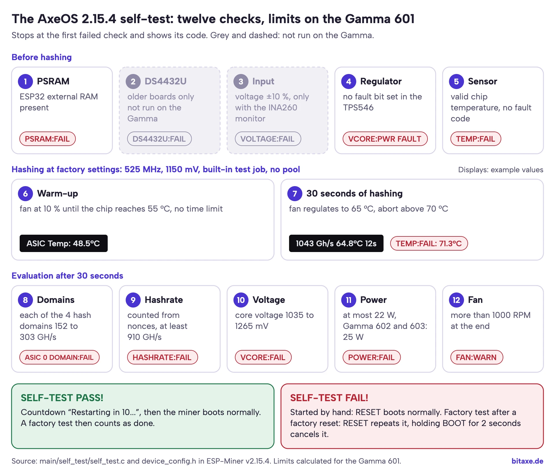
Before the first check, chip detection at boot must have succeeded. If the chip does not answer, the self-test immediately shows that message, such as “ASIC 0 not found”, and stops. The same applies to parts that do not respond at boot: the display then shows, for example, “THERMAL:FAIL” for the temperature and fan chip or “DISPLAY:FAIL”.
| No. | Check | Code on failure | Limit on the Gamma 601 |
|---|---|---|---|
| 1 | ESP32 external RAM (PSRAM) present | PSRAM:FAIL | must be present |
| 2 | DS4432U voltage chip, older boards only | DS4432U:FAIL | not run |
| 3 | Input voltage, only boards with the INA260 monitor | VOLTAGE:FAIL | not run, otherwise ±10 % of nominal |
| 4 | Voltage regulator fault bits | VCORE:PWR FAULT | no fault bit set |
| 5 | Temperature sensor returns valid values | TEMP:FAIL | no fault code such as −1 or 127 |
| 6 | Warm-up at 10 % fan | display ASIC Temp: … | to 55 °C, no time limit |
| 7 | 30 seconds of hashing, the fan regulates to 65 °C | TEMP:FAIL: 71.3°C | abort above 70 °C |
| 8 | Each of the four hash domains individually | ASIC 0 DOMAIN:FAIL | 152 to 303 GH/s per domain |
| 9 | Total hashrate, counted from found solutions (nonces) | HASHRATE:FAIL | at least 910 GH/s |
| 10 | Core voltage | VCORE:FAIL | 1035 to 1265 mV |
| 11 | Power; on multi-phase regulators each phase at least 1 A first | POWER:FAIL, BUCK:FAIL | at most 22 W |
| 12 | Fan speed | FAN:WARN | more than 1000 RPM |
During the 30 seconds the display shows a line in the format “1043 Gh/s 64.8°C 12s”: hashrate, temperature and seconds left; the numbers here are just an example. At the end it shows “SELF-TEST PASS!” with the countdown “Restarting in 10...”, after which the miner boots normally. Note that “VCORE:FAIL” can mean two things: at boot, that the regulator does not respond, and in check 10, that the measured core voltage is outside the window. The log tells them apart (“VCORE init failed” versus “Core voltage test failed”).
Limits by model
AxeOS calculates the limits from the factory values: frequency times the number of small cores times the number of chips gives the expected hashrate, of which the BM1370 must reach 85 % and the BM1368 80 %. Each hash domain may deviate from the average by a third, the core voltage per chip by 10 %. The power limit is a fixed target per board plus 3 W of headroom, plus 21 W on the Gamma Hex.
| Device | Chips | Frequency and voltage in the test | Hashrate at least | per hash domain | Power at most | Core voltage per chip | Fan more than |
|---|---|---|---|---|---|---|---|
| Gamma 601 | 1 × BM1370 | 525 MHz, 1150 mV | 910 GH/s | 152 to 303 GH/s | 22 W | 1035 to 1265 mV | 1000 RPM |
| Gamma 602, 603 | 1 × BM1370 | 525 MHz, 1150 mV | 910 GH/s | 152 to 303 GH/s | 25 W | 1035 to 1265 mV | 1000 RPM |
| GT 801 | 2 × BM1370 | 525 MHz, 1150 mV | 1821 GH/s | 152 to 303 GH/s | 39 W | 1035 to 1265 mV | 500 RPM |
| Supra Hex 702 | 6 × BM1368 | 490 MHz, 1166 mV | 3001 GH/s | 84 to 166 GH/s | 93 W | 1050 to 1282 mV | 1000 RPM |
| Gamma Hex 1300 | 6 × BM1370 | 690 MHz, 1200 mV | 7179 GH/s | 200 to 398 GH/s | 161 W | 1080 to 1320 mV | 500 RPM |
To check the math on the Gamma: 525 MHz × 2040 cores gives 1071 GH/s, the expected hashrate in the dashboard. 85 % of that is 910 GH/s. The Gamma 602 and 603 get 3 W more headroom than the 601; according to the firmware, that is the only difference between the revisions in the self-test.
Reading the result and ending the test
If the miner passes, it restarts on its own after ten seconds, and a factory test then counts as done. If it fails, the result stays on screen and the line below it tells you what to do next:
- After starting with BOOT: “Press RESET button to restart.” Pressing RESET boots the miner normally.
- For the factory test after a factory reset: “Hold BOOT button for 2 seconds to cancel self-test, or press RESET to run self-test again.” Here RESET runs the test again, and it does so on every restart until it passes. If you hold BOOT for two seconds, AxeOS clears the flag and the miner boots normally.
That explains a miner that shows “BITAXE SELF-TEST” again after every restart: it is not stuck, it is repeating a failed factory test. The code on the display tells you why.
What the self-test does not prove
- On the Gamma it does not measure the input voltage. Check 3 only exists on older boards. A weak power supply only shows up if it sags so far within half a minute that the regulator shuts down. For power supply questions, the pause test is the better tool.
- It only tests the factory settings. It does not tell you whether your chip can handle your overclock.
- It takes half a minute. Faults that only appear after hours of heat are not caught.
- Very strong cooling can get in its way. The warm-up phase has no time limit: if the chip does not reach 55 °C at 10 % fan, for example in a cold room or under a large copper cooler, “ASIC Temp: …” stays on the display indefinitely. And because the fan then regulates to 65 °C and may go down to 10 %, it can miss the speed limit with very good cooling and report FAN:WARN. Both follow from the code; we have not measured whether this happens with a particular cooler. If it does, repeat the test in a warmer room.
“ASIC 0 not found” and chip count 0
The message sounds like a dead chip. At first, though, it only means that no chip answered the query for its ID at boot.
How AxeOS detects the chip
At boot, the ESP32 resets the chip over its reset line and sends a broadcast over the serial line. Every chip answers with its ID, the BM1370 with 0x1370, and AxeOS counts the valid answers. With several chips, data, clock and reset are passed from chip to chip; the board forms a chain. If the count does not match, the log shows:
0 chip(s) detected on the chain, expected 1
ASIC 0 not found
ASIC initialization failed - chip chain detection failed
The display shows “ASIC STATUS:” with the message scrolling below it. Mining does not start, the rest of AxeOS keeps running, so the dashboard stays reachable. With several chips, the message lists the missing indices, such as “ASIC 2,3,4,5 not found” when only two of six answer on a Supra Hex. Be careful with the interpretation: AxeOS only counts answers and does not know which chips answered. Because the signals run through the chain, though, the break is probably behind the last chip that still answers.
Wrong firmware or wrong board
If the log shows “CHIP_ID response mismatch: expected 0x1368, got 0x1370”, a BM1370 is answering, but the firmware expects a BM1368. The firmware or board version belongs to a different device, in this example a Supra on a Gamma. The chip is fine. The same applies to “Unexpected ASIC 1 detected”: more chips answer than the board version provides for. Check the “Board Version” on the System page, 601, 602 or 603 on the Gamma, and if it does not match, reinstall the matching firmware with the flasher and a factory reset. How that works is shown in the AxeOS update guide.
When the board version is right
Then the chip is missing one of its prerequisites: core voltage, the two auxiliary voltages, the clock, a clean reset signal or the serial connection. The easiest to rule out is a missing core voltage. Check the log for a Power Fault or “Voltage requested … is out of range” before it. Without core voltage the chip cannot answer, and detection reports it as missing even though it is intact.
- Unplug the power supply completely, wait ten seconds, plug it back in.
- Under Settings, set Core Voltage and Frequency to the entries marked “(Default)”, then Save and Restart.
- Check the board version, and if necessary do a factory reset with the flasher.
- Start the self-test. If it shows “ASIC 0 not found” again, the fault is reproducible.
- Look at the board: burn marks, torn-off components or damage to the jack are a clear case for support.
If “ASIC 0 not found” persists with factory settings, the right firmware and no Power Fault, the fault is on the board. There is nothing more you can check without equipment; the next step is support.
Overheating: chip, regulator and the AxeOS protection
AxeOS watches two temperatures: the chip’s, measured on the Gamma through a diode inside the BM1370, and the voltage regulator’s, which the TPS546 reports itself (VR Temp). From 70 °C at the chip or 105 °C at the regulator, the dashboard warns with “Danger: High Temperature”. Above 75 °C at the chip or above 105 °C at the regulator, the protection kicks in.
What happens then and how to clean up afterwards is described step by step in Making a Bitaxe quieter. In short: AxeOS stops mining, turns off automatic fan control and sets the fan to 100 %, waits at least 30 seconds and until the regulator is below 95 °C, and then continues with 100 MHz less frequency and 100 mV less voltage. It saves both. Three points matter for diagnosis:
- The values stay lowered. Every further trip lowers them again. A hashrate far below Expected after an overheat event is therefore not a defect but the lowered frequency.
- The 1000 mV trap. On the Gamma, core voltages below 1100 mV turn into a Power Fault, see above.
- False alarms from sensor faults. An open bug report describes how the protection also reacts to sensor fault codes (issue 2000): the fan chip reads an open measuring diode as exactly 127 °C, and a disturbed sensor bus produced “OVERHEAT! VR: 16384.000000C ASIC: 64.250000C” there. According to the report, the trigger was a defective display sitting on the same bus. Implausible values in the OVERHEAT line therefore point to the bus or a sensor, not to heat.
About the regulator: for continuous operation, the overclocking guide considers up to 85 °C fine. If VR Temp rises while the chip temperature stays normal, lower frequency and voltage help fastest, because less current then flows through the regulator and it produces less waste heat. NerdOS on the Nerdaxe and NerdQaxe has its own limits and messages such as “MINER OVERHEATED” and “VREG OVERHEATED”; those are covered in the overclocking guide as well.
Fan: “Fan Control Failed” and FAN:WARN
The fan shows up in AxeOS in three ways:
- “Fan Control Failed (Auto)” in the dashboard. The firmware tried to set the speed and the EMC2101 fan chip did not accept the command. That is a communication fault on the board, not a tired fan. AxeOS treats it as a hardware fault and stops mining so the chip does not run without cooling. The brackets show the mode in which it happened, such as Auto, Manual or Startup. The log says “FATAL: Fan Control Failed (Auto). Flagging hardware fault.” A restart resets the fault; if it comes back, it is a case for support.
- 0 RPM while mining in the Fan card or the “Fan RPM” chart. The fan controller works, but the fan does not spin or its speed signal is missing: plug, cable, a blocked or worn fan. If the chip stays at its normal temperature, probably only the speed signal is missing; if the temperature rises, the fan has really stopped.
- FAN:WARN in the self-test. The speed at the end of the test was below the limit, 1000 RPM, or 500 RPM on the GT and Gamma Hex. With very good cooling that can be a false alarm, see self-test.
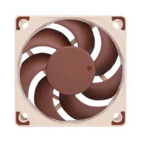
A replacement for the Gamma has to be a 40 mm fan with four pins and 5 V PWM. The swap is shown in Making a Bitaxe quieter, and a quiet replacement is the Noctua NF-A4x20 5V PWM.
Restarts: what Reset Reason tells you
On the System page, Reset Reason shows why the ESP32 last restarted. The reasons come from Espressif’s ESP-IDF framework; AxeOS shows them as fixed English text. The most important ones:
| Reset Reason | Meaning | What to do |
|---|---|---|
Reset due to power-on event | Normal power-up | nothing |
Software reset via esp_restart | AxeOS restarted on purpose: Restart, saving with restart, firmware update, passed self-test | nothing, unless it happens without you doing anything |
Brownout reset (software or hardware) | The ESP32’s supply dipped briefly | Check power supply, cable and plug, Power supply for Bitaxe |
Reset due to power glitch detected | A short voltage fault the chip detected itself | as with a brownout |
Reset due to task watchdog | Part of the program hung longer than allowed, the watchdog restarted it | Keep the firmware up to date; if it happens repeatedly, save the log and report it |
Software reset due to exception/panic | Firmware crash | as with the watchdog; the log from before the crash is preserved |
Reset by USB peripheral | Restart over the USB connection, for example while flashing | nothing |
Only brownout and power glitch point to hardware, and even then first to the supply, meaning power supply, cable and plug. How to get notified about restarts automatically is shown in Monitoring a Bitaxe.
When it is a case for support
After the steps above, only a few cases point to a real defect:
- The self-test fails at factory settings with the supplied power supply, repeatedly at the same step.
- “ASIC 0 not found” persists despite the right board version and a factory reset, with no Power Fault in the log.
- A Power Fault with “An output overvoltage fault has occurred” at factory settings.
- “Fan Control Failed” comes back after every restart.
- A hash domain fails permanently in the self-test (“ASIC 0 DOMAIN:FAIL”), even with a cool chip.
To help us answer quickly, send us:
- model, board version and firmware version from the System page
- a photo of the display with the self-test result
- the downloaded log, ideally including the first occurrence of the fault
- the Reset Reason
- which power supply and cable you use, whether you overclocked and which firmware was running
- photos of the board if anything is visible
You can reach us via Help & Support and the Contact page. Whether there is a defect, we check case by case. For consumers, the statutory rights in case of defects apply. Under section 9.3 of our terms and conditions, there are no such rights where a defect results, for example, from overclocking, an unsuitable power supply or unauthorised changes to hardware or firmware. That is why we ask about power supply, overclocking and firmware.
Frequently asked questions
What does “Power Fault Detected. Check your Power Supply.” mean on a Bitaxe?
How do I start the self-test on a Bitaxe Gamma?
How long does the self-test take?
Why does my Bitaxe keep starting the self-test?
What does “ASIC 0 not found” or chip count 0 mean?
Is my Bitaxe broken if the self-test fails?
Why does the self-test report FAN:WARN even though the fan is spinning?
What temperature is normal for the voltage regulator?
Why does my Gamma show “Power Fault” after overheating?
What does “Brownout reset” on the System page mean?
Does a firmware update help with hardware faults?
What should I send to support for a hardware fault?
Sources
- bitaxeorg/ESP-Miner (AxeOS), release v2.15.4 of 21 October 2026: self_test.c (checks, codes, limits), TPS546.c (status word, log lines, limits per model), power_management_task.c (overheat protection), asic_common.c (chip detection), device_config.h (factory values per board), fan_controller_task.c (fan fault), flashing.md (self-test after flashing)
- ESP-Miner pull request 1790 (minimum voltage after overheating, in the development branch since 14 September 2026) and issue 2000 (overheat protection reacts to sensor faults, open)
- Texas Instruments: TPS546D24A, datasheet SLUSDN0A, sections STATUS_BYTE, STATUS_WORD, STATUS_VOUT, STATUS_INPUT and CLEAR_FAULTS
- bitaxeorg/bitaxeGamma: README and schematic of revision 601 (power supply, plug, components)
- Espressif: ESP-IDF, Reset Reason and esptool, Boot Mode Selection (GPIO0 and flash mode)
Matching products


Read more
Bitaxe security: AxeOS login and password, home network, hotspot and remote access
AxeOS never asks for a password: anyone on the same network can change the pool and the payout address. Which gaps are open as of October 2026, how to separate the miner on your home network, reach it without port forwarding and notice a foreign address right away.
Guides & knowledgeMonitoring a Bitaxe: catch outages, heat and wrong payouts without false alarms
Which values the AxeOS API really delivers, when “no share for …” is a real outage, why a Bitaxe runs slower for good after overheating, and how a small script on your home network watches heat, power, fallback pool and coinbase.
Guides & knowledgeNerdaxe Gaia: what the BM1373 miner can do, which firmware to run and who it is for
A single BM1373 in the familiar Nerdaxe format: factory settings from the source code, hashrate and power draw with every documented figure, the 12-volt power supply, OSM-OS from the flasher, setup, overclocking up to the current limit, block odds and electricity cost, plus a comparison with the Nerdaxe Gamma, Bitaxe GT and NerdQaxe++.